




 Global Finds
  Quick Commerce
  Daily Bazar
  Electronics & Appliances
  Mother, Baby & Toys
  Beauty
  Sports
  Automotive
  Stationery, Books & Music
 _20.png) Fashion Luxe
Fashion Luxe  Jersey
  Sports Shoes
  Fashion
 _20.jpeg) Home
Home  Garden & Pet Care
  Special Weekly Offer
  Grocery
  Global Finds
  Quick Commerce
  Daily Bazar
  Electronics & Appliances
  Mother, Baby & Toys
  Beauty
  Sports
  Automotive
  Stationery, Books & Music
 _20.png) Fashion Luxe
Fashion Luxe  Jersey
  Sports Shoes
  Fashion
 _20.jpeg) Home
Home  Garden & Pet Care
  Special Weekly Offer
  Grocery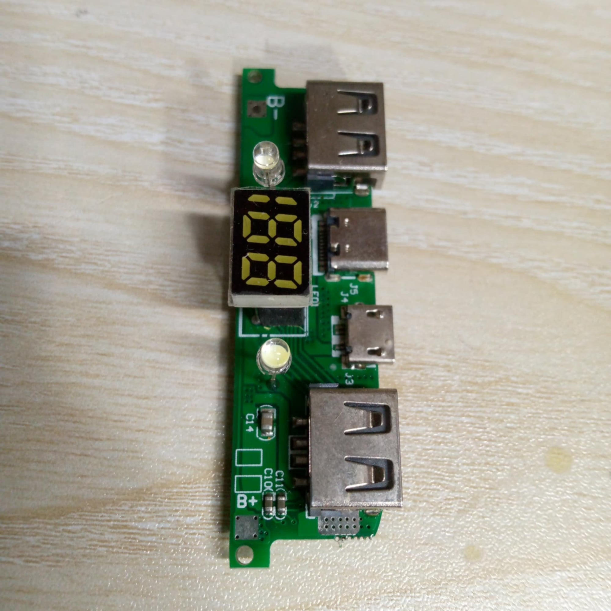
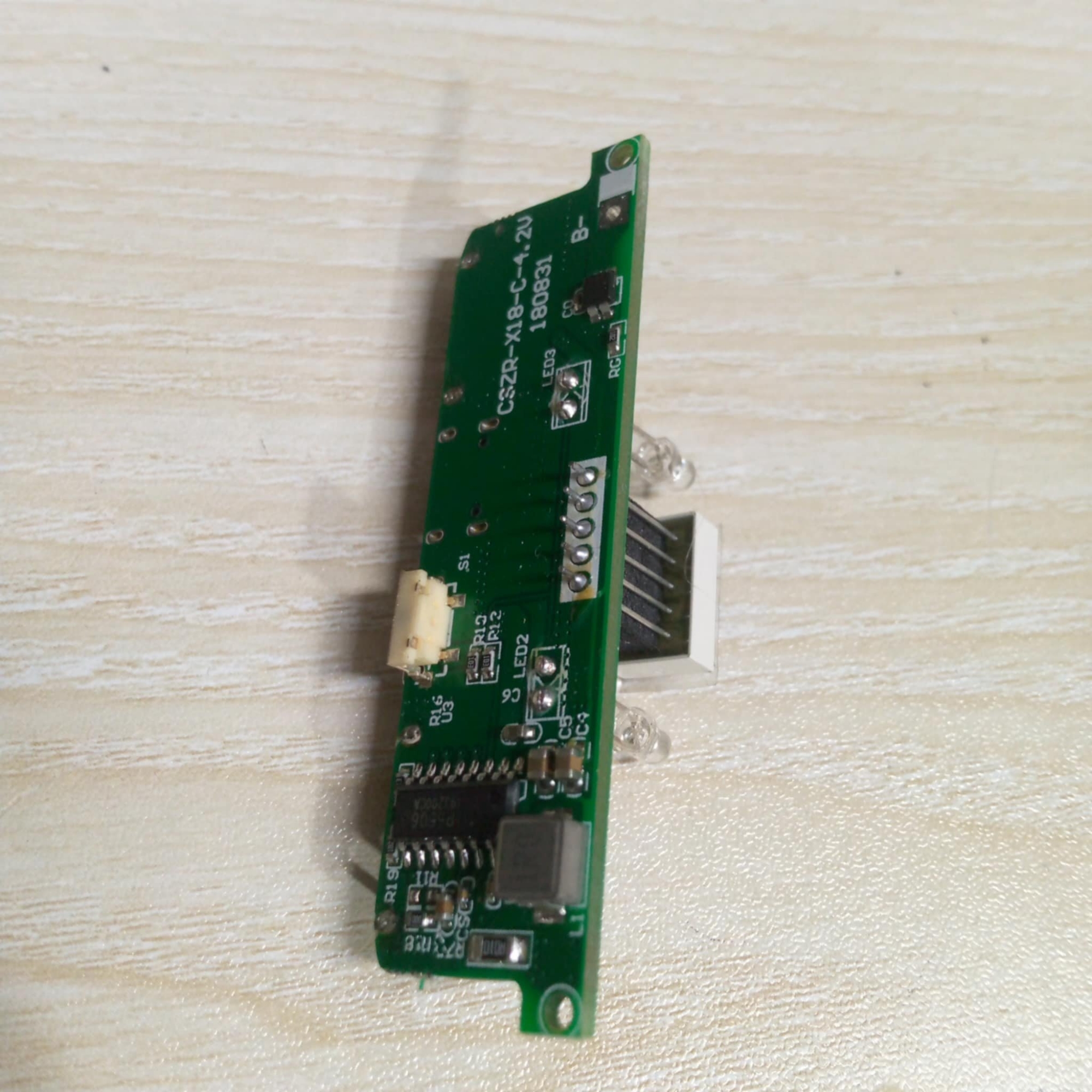
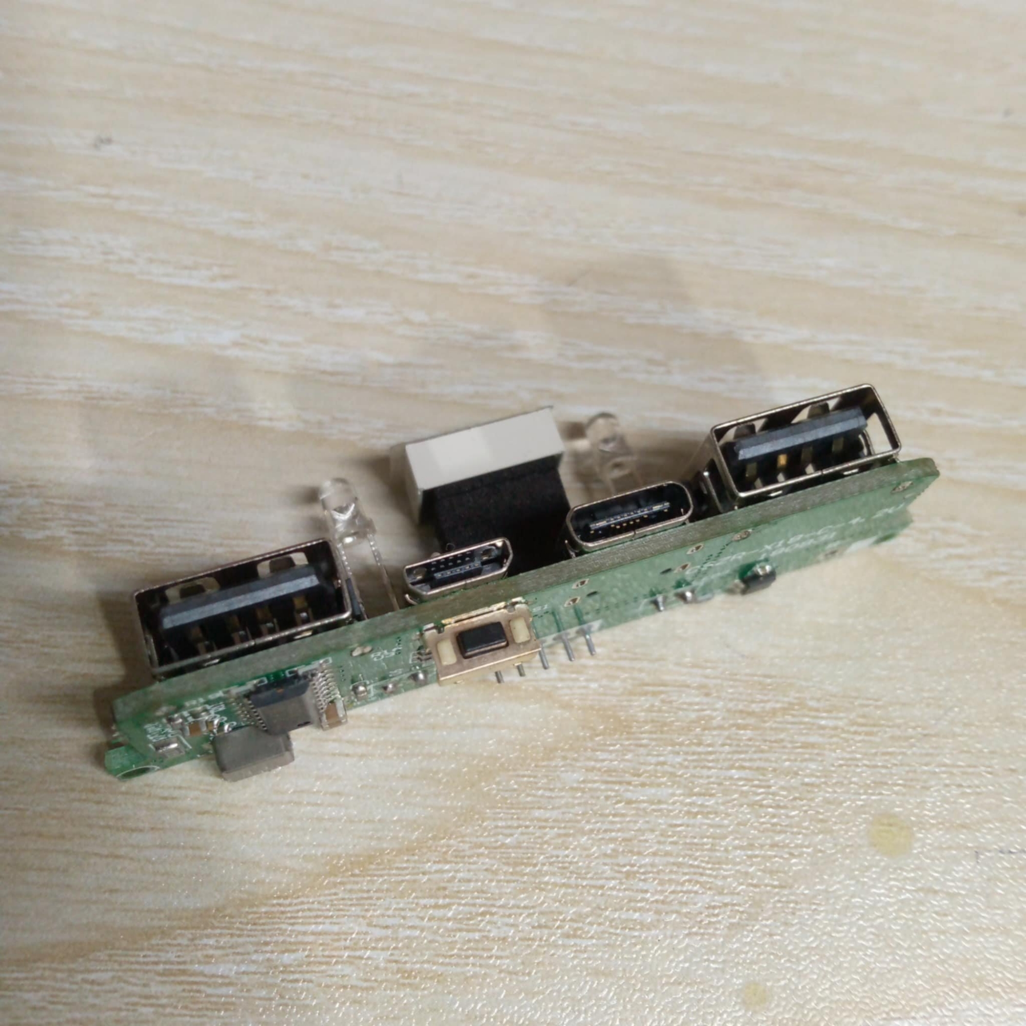
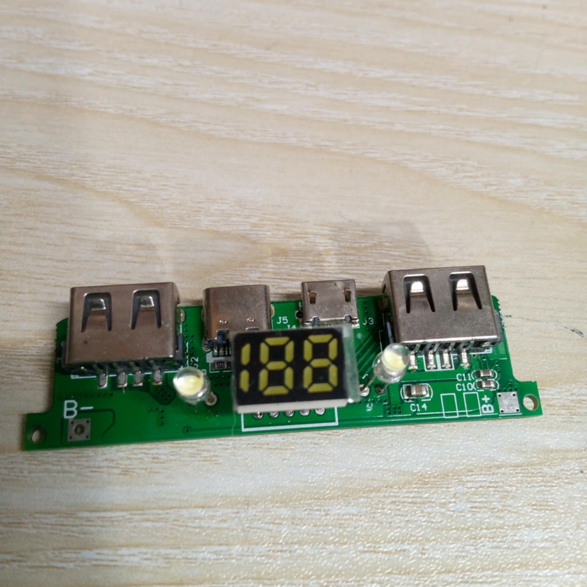
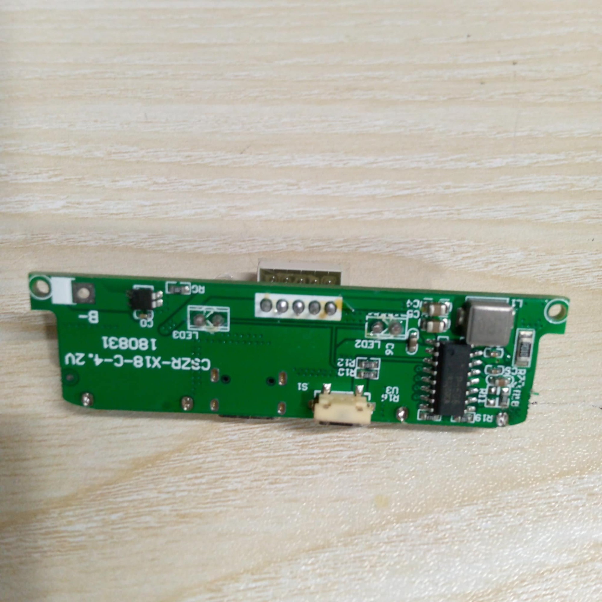
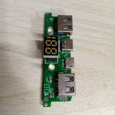
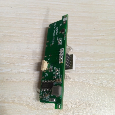
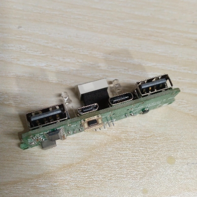
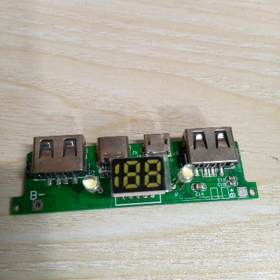
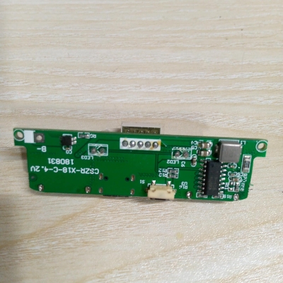
Parallel battery requirements between 3.2-4.2V can work properly, the maximum can not exceed 200,000mA. Power Bank Circuit Dual USB DC 5V 2A Output 5V 2A Input Micro USB With LED Indicator & BMS Protection Lithium Battery 18650 Mobile Smart Phone Charging Module
Features:
- With a torch LED lamp (long press power button to turn ON or OFF).
- Module has multiple safety circuits.
- Output voltage and current is stable, to protect USB devices during charging.
- Module has protection from overcharge, over Discharge, short circuit and no need to worry about the time of charging.
- Battery Level Display:4 LED light to display capacity, in non-operating state, intelligent power off.
Specifications:
- Material: PCB+ Metal
- Connector Type: Micro USB, Type-C,
- IR of PCM : ≤65 mΩ
- Charging cable: support three type of USB Cables for Android Type-C & Micro USB
- Button function: Press and hold the button after standby
- Prevent Overcharge Protection
- Constant current: 2.1A
- output current: 5V 2.1A
- Max continuous charge/discharge current: 1.5/2.1A
- Input voltage B+ to B-: 3.0 – 4.2V
- Suggest working temperature: -5~45℃
- Item Size: 65×30x15mm
- Item Weight: 15gm
Charging Display:
- When charging, battery level 0-25% one light is on, other lights off;
- 25%–50%,the second light flashes, the first light is continuously on;
- 50%– 75%,the third light flashes, front two lights are continuously on;
- 75%—100%;the fourth light flashes, front three lights are continuously on.
- And four lights are on charging to 100%.
Mainboard Protection Function:
- Overcharge protection
- Over discharge protection
- Overcurrent protection
- Module does not need battery protection board as it has inbuilt battery protection system.
Installation Introduction:
- Circuit board B- connects power negative, B+ connects positive. Don’t inversely connect, it will result in burning of board. Make sure there is insulation between power and circuit when install the battery
- 2A output is not continuous current, it changes according to USB connecting load, automatic current output as per load
- If battery is connected incorrectly, the reverse polarity will burn the circuit. So, make sure to check the battery polarity when connecting.
Special Instruction:
- When connecting the board for the first time, connect the battery and then connect the micro USB charger and charge the battery to full capacity before using.
- It is required to prime the IC, so that it starts and shuts down accurately
Notes:
- The positive pole of the battery is connected to B+ and the negative pole is connected to B-, do not reverse it. If it is reversed, it will burn out!
- There might be some deviation due to manual measurement.

Customer Questions and answers :
Login to ask a question
