




 Global Finds
  Quick Commerce
  Daily Bazar
  Electronics & Appliances
  Mother, Baby & Toys
  Beauty
  Sports
  Automotive
  Stationery, Books & Music
 _20.png) Fashion Luxe
Fashion Luxe  Jersey
  Sports Shoes
  Fashion
 _20.jpeg) Home
Home  Garden & Pet Care
  Special Weekly Offer
  Grocery
  Global Finds
  Quick Commerce
  Daily Bazar
  Electronics & Appliances
  Mother, Baby & Toys
  Beauty
  Sports
  Automotive
  Stationery, Books & Music
 _20.png) Fashion Luxe
Fashion Luxe  Jersey
  Sports Shoes
  Fashion
 _20.jpeg) Home
Home  Garden & Pet Care
  Special Weekly Offer
  Grocery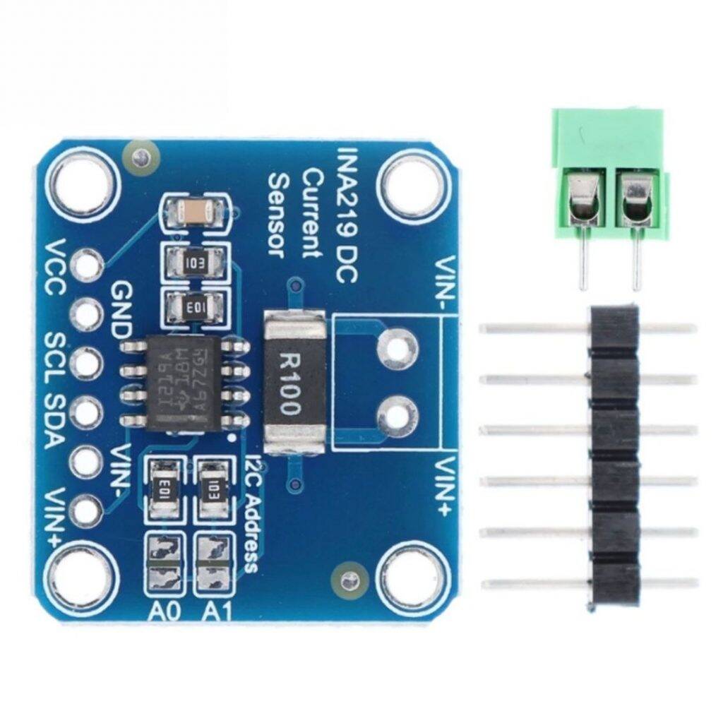
u173473
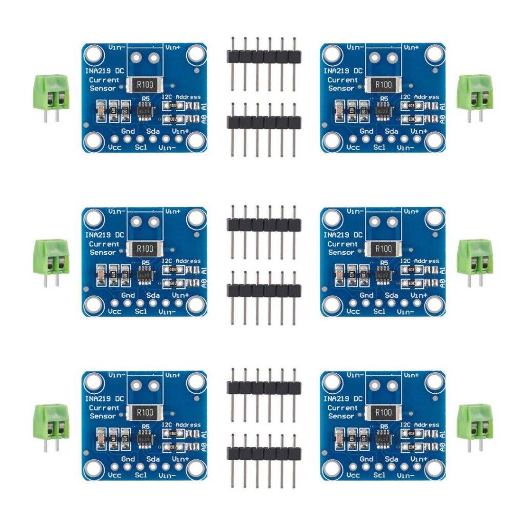
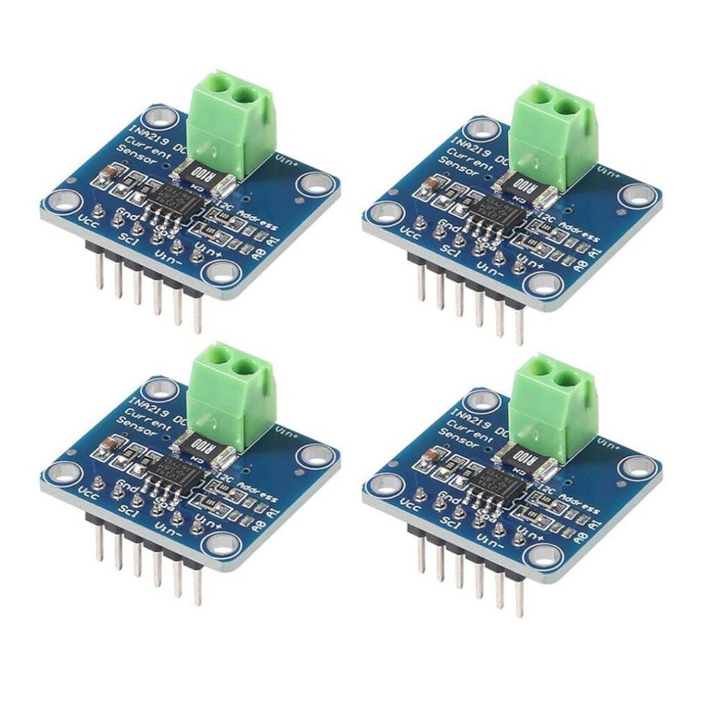
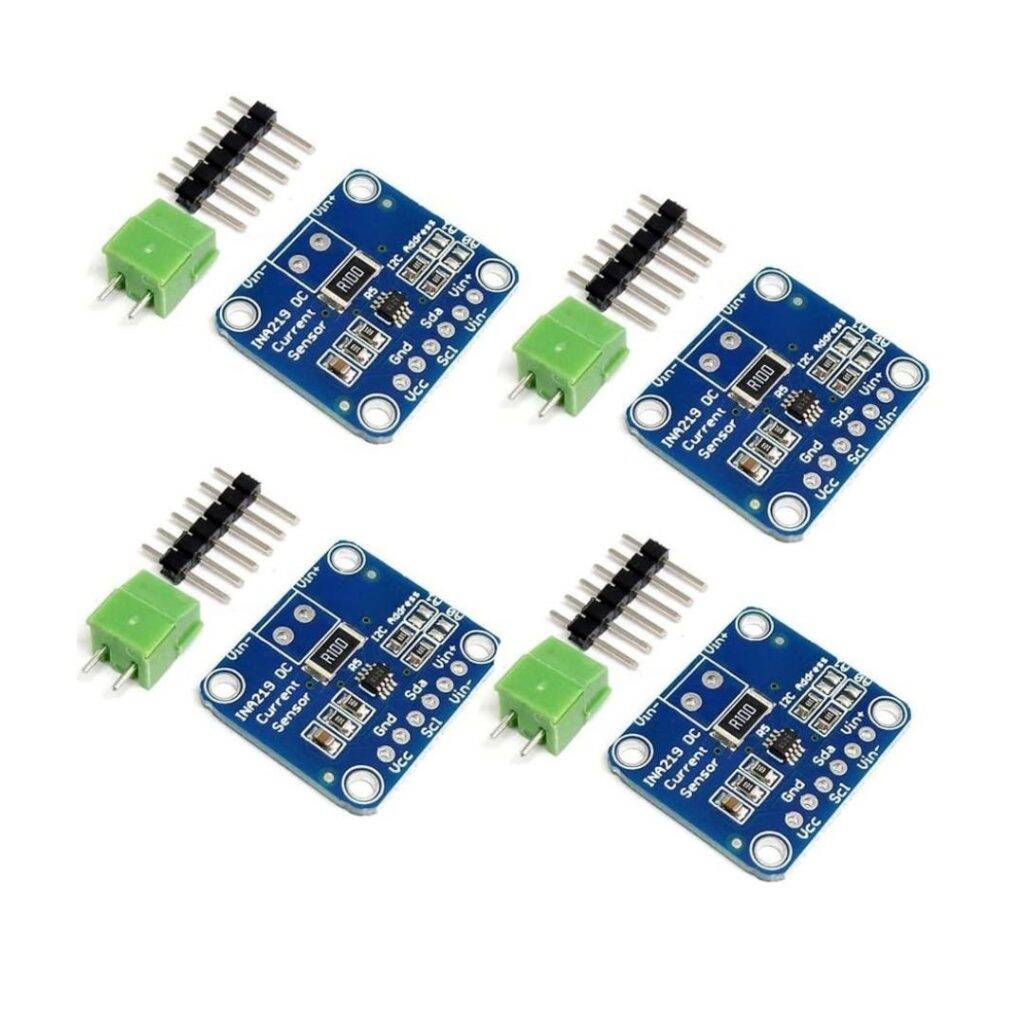
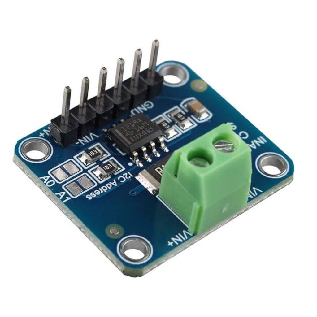
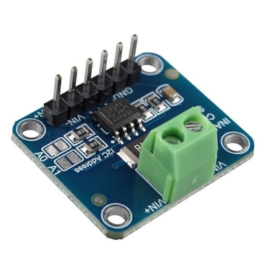
Description: INA219 DC Current & Power Measurement Module
Here’s a detailed breakdown of the INA219 DC Current & Power Measurement Module — how it works, key specifications, how to use it, what to watch out for, and typical applications.
What it is:
The INA219 module is based on the TI‑chip INA219, which is a high‑side current shunt & power monitor with an I²C interface.
In practice the breakout board integrates that chip plus a precision shunt resistor (typically 0.1 Ω) and the necessary pins/headers so you can measure:
- Bus voltage (i.e., the supply voltage of the load)
- Shunt voltage drop (across the resistor) → from which current is calculated
- And from those two, power (voltage × current) is derived by the chip.
Because it performs high‑side sensing (i.e., the shunt is placed in the positive rail to the load) the ground path is left undisturbed
Key Specifications:
Here are the key specs you should know (from module/breakout board plus chip).
Chip (INA219) specs:
- Supply voltage (VCC) for the chip: 3.0 V to 5.5 V
- Bus voltage (voltage being sensed) up to ~ 0 to 26 V.
- I²C/SMBus interface, up to 16 programmable addresses.
- Accuracy: For INA219B version the accuracy is up to ~0.5 % over temperature.
- Internal resolution: 12‑bit ADC for the shunt/bus measurement.
Typical breakout board module specs:
- On‑board shunt resistor: 0.1 Ω, 1% tolerance, ~2 W rating (depending on board).
- Current measurement range: ±3.2 A (with 0.1 Ω shunt) and resolution ~0.8 mA (when configured with default resistor).
- Bus voltage measurement: up to ~26 V DC.
- Module supply/logic compatibility: 3.3 V or 5 V logic (i.e., can be used with Arduino/ESP32/others).
How to Use (Connection & Setup):
Here’s typical steps/setup to use the module:
- Powering the module
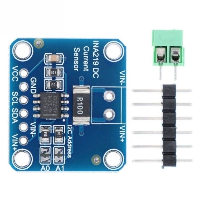
- Connect the module VCC pin to your microcontroller’s 3.3 V or 5 V supply (depending on your board’s version).Connect GND of the module to the same ground as your microcontroller and the load ground (this ensures the bus voltage measurement is correct).
- Current‑shunt wiring (high side)
- The module’s screw terminals (or header) labelled VIN+ and VIN‑ go in the positive supply path of your load:
- Supply positive → VIN+ on module
- VIN‑ on module → load positive terminal
- So the shunt resistor is between the supply and the load. This way, the module “sees” the current going to the load.
- If you only care about voltage and not current, you can connect the bus voltage to VIN+ but you still need ground common. But typically you use VIN+ → supply and VIN‑ → load.
- I²C connection
- Connect SDA and SCL pins of the module to the SDA / SCL pins of your microcontroller.
- If using multiple modules, make sure the I²C address is set via jumpers/solder pads (modules often allow changing from the default 0x40 to e.g. 0x41, 0x44, 0x45).
- Software setup
- Use an appropriate library (e.g., Adafruit’s INA219 library) for your microcontroller.
- In your code you typically configure the calibration register (to set the shunt resistor value and full‑scale current), then you can read: bus voltage (V), shunt voltage (mV), current (A), and power (W).
- Example: If your module’s shunt is 0.1 Ω you set that in calibration so the library computes current = V_shunt / 0.1Ω etc.
Package include:
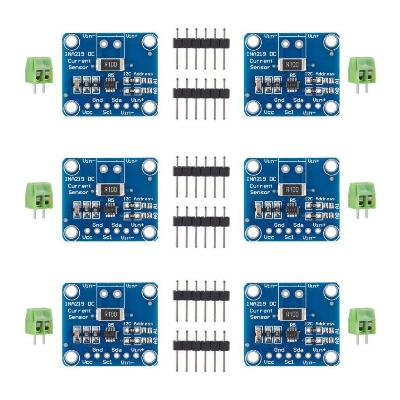
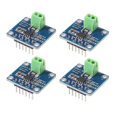
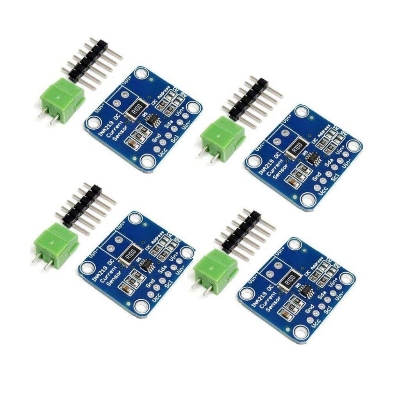
1 x INA219 DC Current & Power Measurement Module

Customer Questions and answers :
Login to ask a question
