




 Global Finds
  Quick Commerce
  Daily Bazar
  Electronics & Appliances
  Mother, Baby & Toys
  Beauty
  Sports
  Automotive
  Stationery, Books & Music
 _20.png) Fashion Luxe
Fashion Luxe  Jersey
  Sports Shoes
  Fashion
 _20.jpeg) Home
Home  Garden & Pet Care
  Special Weekly Offer
  Grocery
  Global Finds
  Quick Commerce
  Daily Bazar
  Electronics & Appliances
  Mother, Baby & Toys
  Beauty
  Sports
  Automotive
  Stationery, Books & Music
 _20.png) Fashion Luxe
Fashion Luxe  Jersey
  Sports Shoes
  Fashion
 _20.jpeg) Home
Home  Garden & Pet Care
  Special Weekly Offer
  Grocery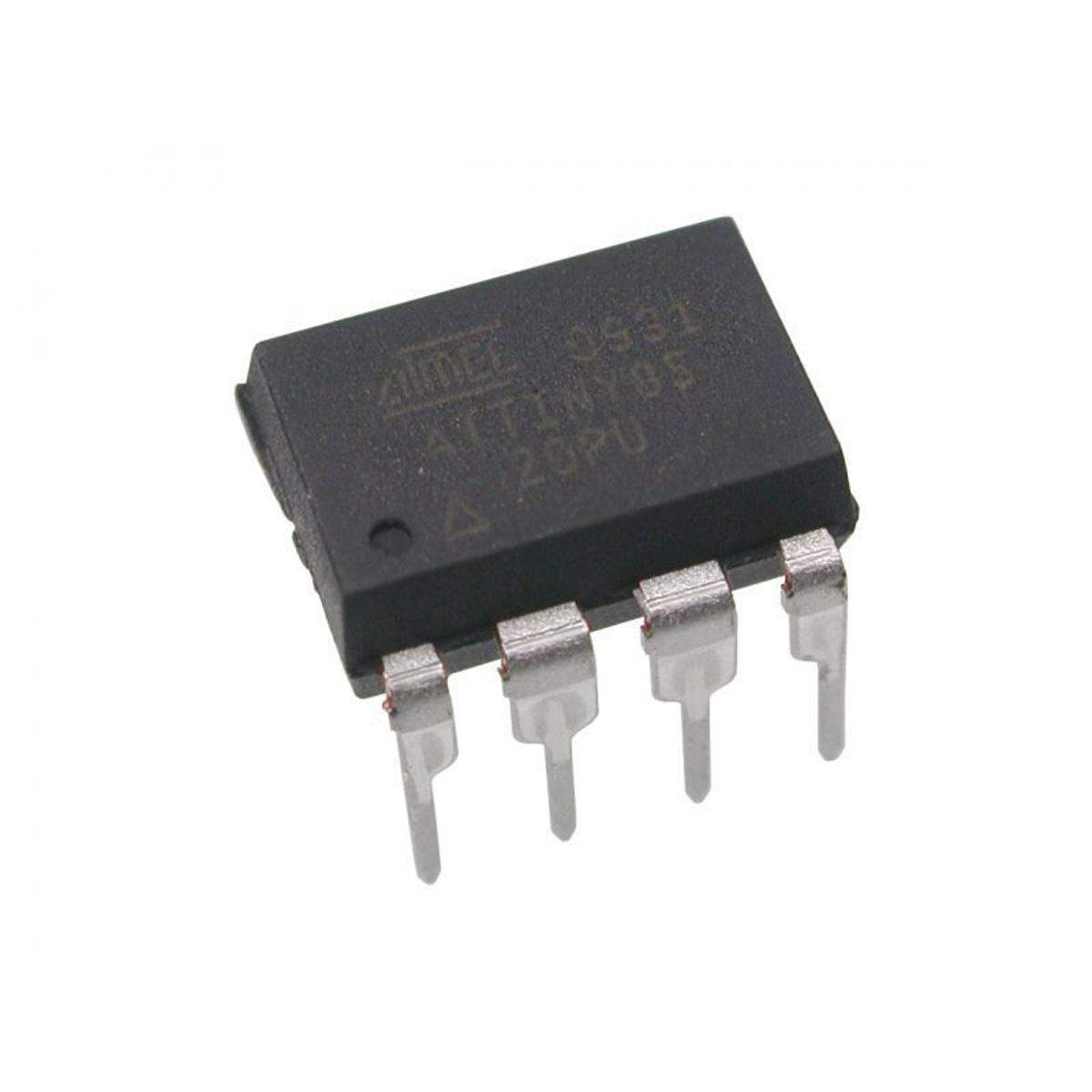
Description: ATTiny45 8-Pin 20MHz 4kb 8-Bit
ATTINY45-20PU ATTINY 45 ATtiny45 Microcontroller DIP-8 AVR Microcontroller EEPROM 256B SRAM 256B Flash 4KB 20MHz IC For Electronics Engineering Project & Industry
The high-performance, low-power Atmel 8-bit AVR RISC-based microcontroller combines 4KB ISP flash memory, 256-Byte EEPROM, 256B SRAM, 6 general purpose I/O lines, 32 general purpose working registers, one 8-bit timer/counter with compare modes, one 8-bit high speed timer/counter, USI, internal and external Interrupts, 4-channel 10-bit A/D converter, programmable watchdog timer with internal oscillator, three software selectable power saving modes, and debugWIRE for on-chip debugging. The device achieves a throughput of 20 MIPS at 20 MHz and operates between 2.7-5.5 volts.By executing powerful instructions in a single clock cycle, the device achieves throughputs approaching 1 MIPS per MHz, balancing power consumption and processing speed.
ATtiny45 Features / Technical Specifications
High efficiency design
Low current consumption 300uA in use & 0.1uA in sleep mode on 1.8V.
Total six analog inputs
built in 4 kbytes of flash memory
built in 256b of SRAM
Built in 256b of EEPROM
Circuitry contains 32 Registers
Minimum cycles per instruction design or Advance RISC
Programming lock feature for code security
Built in two 8-bit timers one is high speed and other is compare mode.
Total six I/O pins
Universal Serial Interface feature
Two pulse width modulation channels
Watchdog programmable Timer & Oscillator
Operating voltage as low as 1.8V DC to 5.5V DC max.
Pin Configuration
PIN# PIN DESCRIPTION PIN FUNCTION PIN DESCRIPTION
1 PB5 PCINT5
ADC0
dW
RESET PB5 is reset pin of the IC, one wire debugging, analog pin, Analog to digital input channel 0, bootloader reprogram and remove, PCINT5
2 PB3 also GPIO3 XTAL1
CLKI
ADC3
OC1B
PCINT3 Clock input from external source, Analog to digital input channel 3, Crystal input, PWM
3 PB4 also GPIO4 XTAL2
CLKO
ADC2
OC1B
PCINT4 Crystal output, clock input from external source, Analog to digital input channel 2.
4 GND Ground Ground / Negative Supply of microcontroller
5 PB0 also GPIO0 MOSI
AIN0
OC0A
OC1A
DI
SDA
AREF
PCINT0 PWM ouput, SPI communication, timer, USI
6 PB1 also GPIO1 MISO
AIN1
OC0B
OC1A
DO
PCINT1 SPI data communication, PWM output, timer, USI
7 PB2 also GPIO2 SCK
ADC1
T0
SCL
PCINT2 Analog to digital input channel 1, timer, USI, clock input
8 VCC Positive Voltage Positive supply of the microcontroller.
ATtiny45 Description
ATtiny45 is a small size microcontroller available in 8 pin dip and other packages. It is a latest design microcontroller & it contains variety of built in features which are not available in that size and kind of microcontroller previously. The internal design is built to obtain very less power which makes it ideal for battery operated, solar powered and portable devices. It can also be used to shrink small arduino projects. However the user must note that it cannot perform as the ATmega328p because due to its size and design it contains less flash memory, EEPROM and SRAM but if the program code is comes under these limits then you are ready to go. Moreover the 4 kilobytes of flash memory 256 bytes of SRAM & 256 bytes of EEPROM is quite enough to run a variety of programs which you run on ATmega328p. For example you can attach sensors, send data and almost any simple task that your perform with arduino.
Applications
There are wide varieties of applications and projects that can be built using the ATtiny45 microcontroller, some of the applications are listed below.
Machinery controlling systems in different industries
Solar based projects
Home, Office, factories IOT based applications
Weather systems & applications
Wireless data transfer & communication applications
Security based projects
Medical & health related devices
Automobile applications
and many more…
Replacement or Equivalent
ATtiny25 and ATtiny85 are the two most suitable alternatives of ATtiny45. But the internal Flash, SRAM and EEPROM values are different of all the three microcontrollers.
How to Use ATtiny45
Like any other microcontroller ATtiny45 require programing code that can be inserted or saved through its ISP software. For doing so all you have require is an ISP and the code of the program you want to run in this microcontroller so first of all you have to make an ISP.
There are different many different ISP options available to program the chip but the most affordable and easy procedure is to make the available arduino UNO board as an ISP which we are going to discuss here but you can also use other methods like any dedicated ISP device that can be connected between your computer and the ATtiny45.
For making arduino UNO as an ISP for ATtiny45 first you need to program the arduino UNO board but don’t worry it’s not that difficult the tutorial mentioned in the below link will provide you all the essential information about it. It can be used to program not only ATtiny85 but also ATtiny45 microcontroller.
Getting long term performance with ATtiny45
The microcontroller chips are sensitive components therefore care must be taking while soldering and operating the device. Below are some of the guidelines to get best and long term performance from Attiny45.
The maximum voltage of the chip is 5.5V therefore do not provide more than that, always make sure to check the voltage with the multimeter before providing to the chip. The max current limit on single I/O pin is 40mA do not increased more than it. Moreover the max current requirement of the chip is 200mA.
Always check the chip pins placement in the circuit diagram before connecting in the circuit. Wrongly connecting the pins may result in internally damaging the chip. If you are soldering the chip directly to the circuit board do not provide more heat than the recommendation in the datasheet or use an IC socket to get rid of accidentally applying more than recommended heat to the chip.
Do not store the chip in temperature below -65 Celsius and above +150 Celsius and operate above -55 Celsius and below +125 Celsius.

Customer Questions and answers :
Login to ask a question
