




 Global Finds
  Quick Commerce
  Daily Bazar
  Electronics & Appliances
  Mother, Baby & Toys
  Beauty
  Sports
  Automotive
  Stationery, Books & Music
 _20.png) Fashion Luxe
Fashion Luxe  Jersey
  Sports Shoes
  Fashion
 _20.jpeg) Home
Home  Garden & Pet Care
  Special Weekly Offer
  Grocery
  Global Finds
  Quick Commerce
  Daily Bazar
  Electronics & Appliances
  Mother, Baby & Toys
  Beauty
  Sports
  Automotive
  Stationery, Books & Music
 _20.png) Fashion Luxe
Fashion Luxe  Jersey
  Sports Shoes
  Fashion
 _20.jpeg) Home
Home  Garden & Pet Care
  Special Weekly Offer
  Grocery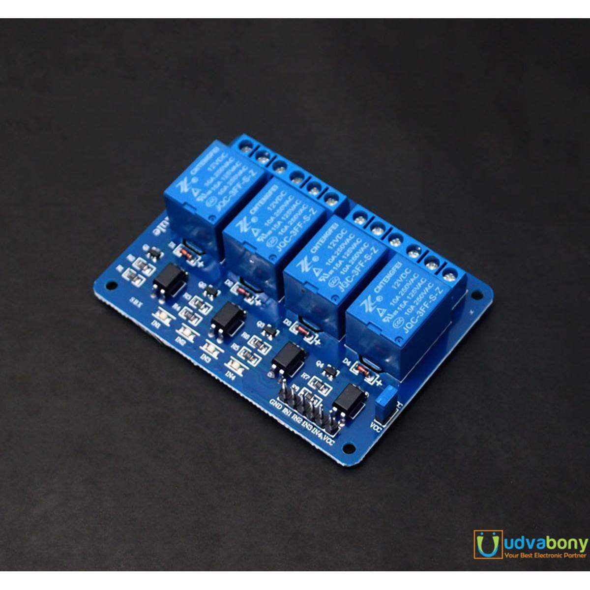
Descriptions: DC 12V 4 Channel Relay Module
4 Channel Relay Module board is used to interface any Microcontroller with Electrical Appliances/Loads. Can also be used in driving high power motors.4-channel relay output modules, relay output contacts 250A 10A. Input IN1, IN2, IN3, IN4, the signal line LOW effective. VCC, GND power input, can relay a separate power supply relay power input of JD-VCC.
What is a Relay?
Arelayis an electrically operated switch. Many relays use an electromagnet to mechanically operate a switch, but other operating principles are also used, such as solid-state relays. Relays are used where it is necessary to control a circuit by a separate low-power signal, or where several circuits must be controlled by one signal.
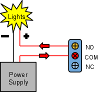
Relays work on electromagnetism, When the Relay coil is energized it acts like a magnet and changes the position of a switch. The circuit which powers the coil is completely isolated from the part which switches ON/OFF, This provides electrical isolation. This is the reason we can control a relay using 12V’s from an arduino and the other end of it could be running an 220 to 240V appliance, the 240V end is completely isolated from the 12V .
Overview:
- Channel: 4 channel
- Relay Operating Voltage: 12V
- Triode drive, increasing relay coil
- High impedance controller pin
- Pull-down circuit for the avoidance of malfunction
- Power supply indicator and Control indicatorlamp
- Power supply and relay instructions, lit, the disconnect is off;
- The input signal, signal, common Terminal and start conducting;
Specifications:
- Module can be controlled directly by Microcontroller (Raspberry Pi, Arduino, 8051, AVR, PIC, DSP, ARM, ARM, MSP430, TTL logic)
- Easy to install and fix
- Optically Isolated relays to protect your microcontroller from damage if the equipment being controlled fails
- four screw holes, hole diameter 3.1mm
- relay status indicator light, release status LED is off
- Relay Maximum output: DC 30V/10A, AC 250V/10A
- Size: 75mm (l) x 55mm (b) x 19.3mm (h)
- Weight: 58g
- PCB Color: Blue
How to connect:
The connections to your Arduino (or microcontroller) side:
- VCC – supply voltage. 12V
- IN1 – set to HIGH to set the relay to its “default” state, set to LOW to switch the relay to its alternate state
- IN2 – same as IN1, but controls the second relay on the board
- IN3 – same as IN1, but controls the second relay on the board
- IN4 – same as IN1, but controls the second relay on the board
- GND – ground
Application:
- Smart home control
- Industrial sector
- Fan/lighting control
- 5-12 VDC automotive applicatio
- support all MCU control.
- the industrial sector;
- PLC control;
- smart home control;
Package include:
- 1 x 12v 4 Channel Relay Module

Login to ask a question
